01
Upload the drawing
Start with a PDF, PNG or JPEG of a dimensioned mechanical part. Include readable dimensions, units and clear front, side or section views.
We’re developing a workflow from scanned mechanical drawings to editable 3D CAD, with STEP export for your engineering tools.
Engineering-aware. Dimension-driven.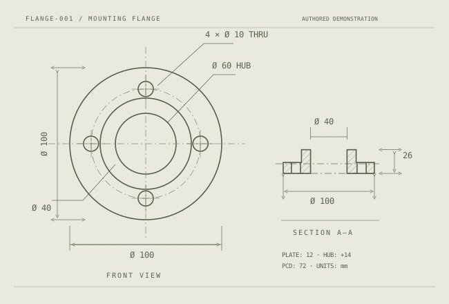
 Ø 10012 mm
A planned workflow for dimensioned mechanical drawings. Views, units and tolerances guide reconstruction; engineering review checks the result against the source.
Start with a PDF, PNG or JPEG of a dimensioned mechanical part. Include readable dimensions, units and clear front, side or section views.
The planned analysis pipeline identifies views, dimensions, tolerances and mechanical features.
Build a parametric definition around engineering geometry. Dimensions become editable parameters.
Inspect the model, resolve ambiguities and use the CAD definition in your engineering workflow.
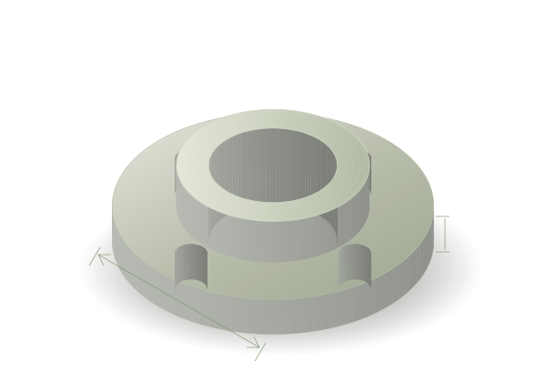
Follow a mounting flange from orthographic views to a parametric CAD definition. The example shows a central bore, bolt circle and raised hub, defined by the dimensions in the source drawing.
# FLANGE-001 · all dimensions in mm
import cadquery as cq

# Start with the drawing dimensions
outer_diameter = 100
bore_diameter  = 40
plate_height   = 12
bolt_circle    = 72

result = (
    cq.Workplane("XY")
      .circle(outer_diameter / 2)
      .extrude(plate_height)
      .faces(">Z").workplane()
      .circle(30).extrude(14)
)

# Continue with the bore and mounting holesSTEP carries solid geometry for CAD exchange. STL and GLB serve mesh and preview workflows. The editable source definition remains available separately.
A Python-based parametric definition you can inspect, change and regenerate.
Solid geometry for exchange with your existing mechanical CAD tools.
Triangulated geometry for prototyping, 3D printing and downstream mesh tools.
A lightweight 3D preview for visual review and sharing in the browser.
For teams recovering mechanical parts from paper and PDF archives when the original CAD is missing. Preserve dimensions, units and revision context throughout the workflow.
Recover a starting CAD definition from archived technical drawings. Keep design knowledge accessible as engineering tools change.
02Rebuild a reviewable model when original CAD is missing. Check critical fits and mating surfaces against the actual component.
03Prepare paper and PDF component drawings for modern 3D workflows. Organise inputs around parts, revisions and units.
04Use dimensioned views as constraints for a starting model. Identify missing information before accepting reconstructed geometry.
05Move legacy drawing knowledge into editable, portable geometry and a CAD definition that can be maintained.
Mechanical drawings describe relationships: a concentric bore, a bolt circle, a section through a hidden cavity. Scan2BIM is being built to carry that information into parametric geometry.
Join the early-adopter listViews, annotations, dimensions and tolerances.
CadQuery definitions with explicit geometric parameters.
Review geometry, flag ambiguity and verify against the source.
L2Labs is an AI development team working in computer vision and 3D software. Scan2BIM explores how dimensioned mechanical drawings can become reviewable CAD models, with engineering checks kept in the workflow.
Know what to expect before
you bring a drawing.
Scan2BIM is being developed to reconstruct editable parametric CAD from scanned, dimensioned mechanical drawings. Join the early-adopter list to share your use case and hear when early access opens.
The initial focus is individual mechanical parts described in PDF, PNG or JPEG engineering drawings. Clear dimensions, units, front and side views, and section views provide useful information for reconstruction.
The planned outputs are CadQuery Python, STEP, STL and GLB. The parametric CadQuery definition will be the editable source; STEP carries exchange geometry, while STL and GLB provide mesh representations.
This website introduces the product and collects early-adopter interest. Drawing uploads and automated reconstruction are not available here yet. The flange shown is an authored example of the intended workflow.
CadQuery is an open-source Python library for describing parametric CAD models. Dimensions and operations such as extrusions, bores and holes form an editable source definition that can be regenerated.
Yes. Dimensions, tolerances, units, feature placement and missing geometry must be checked against the source and intended use. A model preview alone does not establish manufacturing suitability.
The initial product scope is individual mechanical components. Assembly reconstruction would require a separate workflow.
We will use your submitted details to contact you about Scan2BIM early access and, where relevant, discuss your engineering use case. Registration does not create an account or require you to upload a drawing.
Working with legacy mechanical drawings? Join the early-adopter list and help shape a tool built around the parts you need to recover.